ENGR216 Summer 2023 Dynamics Q B2[VALID]
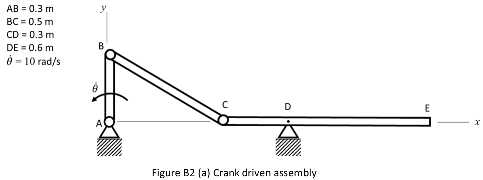
Figure B2 shows a crank driven assembly that comprises three connected slender bars (AB, BC and CDE) that produce oscillatory motion at point E. Each of the bars are of uniform section and have a mass moment of inertia for - rotation about their centre of mass () of , where = mass and = length. Data: AB = 0.3 m, BC = 0.5 m, CD = 0.3 m, DE = 0.6 m, rad/s. For the instant shown:
Formulas you may need
- Rigid-body relative velocity: (learn this)
- Rigid-body relative acceleration: (learn this)
- Instantaneous centre of zero velocity (as a check) (learn this)
- Slender bar: (given in the question)
- Parallel-axis theorem: (learn this)
- Planar kinetics: , ; about a fixed pin (learn this)
- (i)[2]ThirdShow that the velocity of point B is m/s
- (ii)[3]2:2Show that the velocity of point C is m/s
- (iii)[3]ThirdDetermine the angular velocity of bar CDE
- (iv)[6]2:1Determine the angular accelerations of bars BC and CDE
- (v)[5]2:2Determine the acceleration of the centre of mass of BC
- (vi)[6]Given that the mass of BC = 2 kg and the mass of CDE is 3 kg, determine the forces exerted on BC by the pins at B and C.