ENGR217/266 Summer 2022 Q A1[VALID]
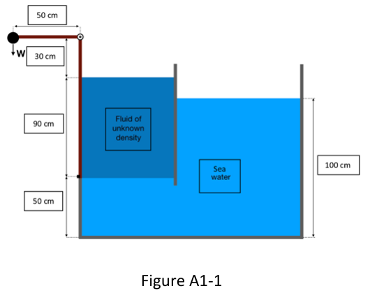
A tank is divided in two compartments as shown in Figure A1-1. The left compartment contains a fluid of unknown density (darker area in the Figure A1-1), confined on the left by an L-shaped gate. A beam holding a mass of weight W is hinged to the gate as shown in the Figure A1-1. The rest of the gate is filled with water (light blue region, seawater density is ).
Formulas you may need
- Hydrostatic pressure: ( = depth) (on the formula sheet)
- Force on a plane surface: (on the formula sheet)
- Centre of pressure: (on the formula sheet)
- Rectangle: , (on the formula sheet)
- Moment equilibrium about the hinge: (learn this)
- (a)[6]Using the fluids levels indicated in the figure, determine the density of the unknown fluid occupying the leftmost portion of the tank.
- (b)[6]Using the value of the density computed in A1-(a), determine the force exerted by the fluid on the gate (assume that the width of the gate, i.e. its size in the direction normal to the paper is 2 m).
- (c)[6]Determine the location of the centre of pressure on the gate.
- (d)[4]Draw a free body diagram incorporating the weight W and the hydrostatic force exerted by the fluid in the tank into the gate.
- (e)[3]Determine the minimum value of the weight W that keeps the gate closed (gate does not rotate about the hinge).