ENGR216 Summer 2017 Q A1[VALID] official answers
Answer ALL parts (a) - (e)
Formulas you may need
- Axial deformation of a uniform segment , summed over segments (learn this)
- Normal stress and Hooke's law (learn this)
- Area of a solid circle (on the formula sheet)
- Equilibrium along the bar (learn this)
- Compatibility for a bar between rigid supports: total change in length ; method of superposition (release a redundant support, then restore it) (learn this)
- (a)[4]ThirdExplain what the difference between statically determinate and statically indeterminate structures is, and explain what is the standard procedure for determining all reactions for these two types of systems.
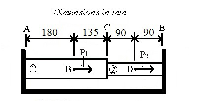
- (b)[3]ThirdConsider the structure depicted in Figure A1. The structure is made up of two cylindrical rods denoted by (1) and (2) joined at C and restrained by rigid supports at A and E. State whether the structure of Figure A1, constrained to maintain the same overall lengths between positions A and E before and after applications of the concentrated loads and , is statically determinate or indeterminate, and justify your answer.
- (c)[3]ThirdExplain which conditions can be used to determine the reactions at the rigid supports A and E.
- (d)[8]The cross section diameter and Young's modulus of rod (1) are respectively and , and the corresponding parameters of rod (2) are respectively and . The values of the axial loads and indicated in Figure A.1 are and , and all four lengths indicated in the figure are in millimetres. Determine the reactions at the rigid supports A and E, providing their magnitude and orientation (left or right).
- (e)[7]Determine the magnitude and direction (left or right) of the displacement of point c.