ENGR216 Summer 2025 Q A1[VALID] official answers
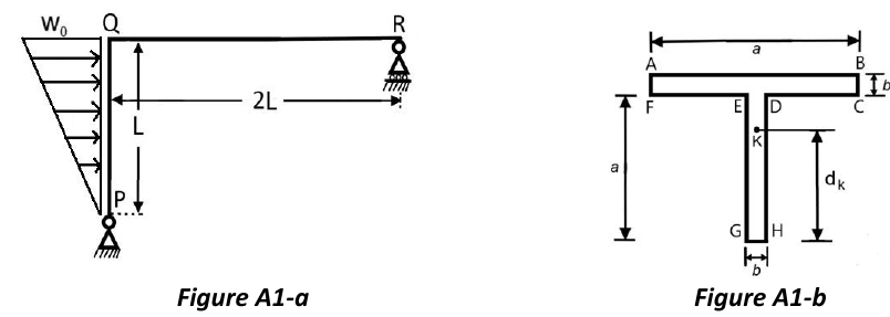
Figure A1-a shows a structure of negligible mass constrained by a pin at end P and a roller at end R. Member PQ is loaded by a linear distributed load , which is 0 at end P and equals at end Q, with denoting the position along member PQ. The coordinate along member QR, with origin at Q, is denoted by .
Formulas you may need
- Resultant of a distributed load and its line of action (on the formula sheet)
- Equilibrium , , ; a pin gives two force components, a roller one force normal to its surface (learn this)
- Load, shear and moment: , , with the positive shear and positive bending pictures (on the formula sheet)
- Transverse shear stress with (first moment about the neutral axis of the area on one side of the point) (learn this; on the 2025 sheet but not the 2026 one)
- Radius of gyration (on the formula sheet)
- Rectangle (on the formula sheet); parallel-axis theorem and centroid of a composite area (learn this; only needed to check the given data)
- (a)[4]2:2Draw the free-body-diagram of the entire structure, indicating ONLY the nonzero reactions and applied loads.
- (b)[6]2:2Calculate the reactions acting on the considered structure.
- (c)[4]2:2Knowing that the expression of the bending moment along member PQ is: and the expression of the bending moment along member QR is: determine the expression of the sharing load along PQ and the shearing load along QR.
- (d)[4]2:2Draw as accurately as possible the shearing and the bending moment diagrams along PQ and QR, consistently with the expressions given or obtained above.
- (e)[7]Calculate the minimum length required for the magnitude of the maximum shearing stress in the cross section of member PQ at end P not to exceed 10 MPa. The cross section is reported in Figure A1-b. Use mm, mm and kN/m. The section is positioned so that the neutral axis of the bending moment is parallel to side AB. The centroid K of the section is at distance of 120 mm from side GH, and the radius of gyration past the neutral axis is 54.8 mm.