ENGR216 Statics "new problem 2" (set in session 11, solved in session 14) official answers
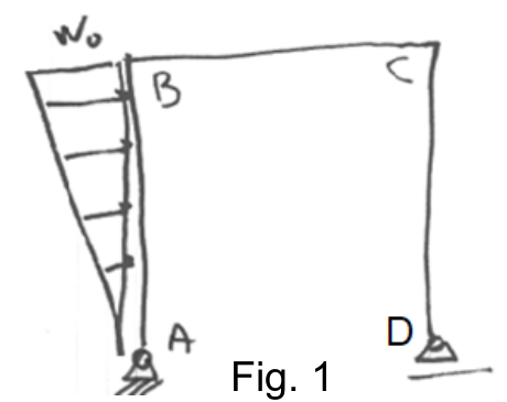
The structure in Fig. 1 is made of columns AB and CD rigidly connected to beam BC. All three members have length . A is pinned and D rests on a roller (vertical reaction only). Column AB carries a triangular distributed load acting horizontally to the right, growing linearly from zero at A to at B, i.e. with measured along AB from A.
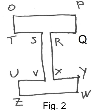
All members have the I cross section of Fig. 2: flange width mm, web height mm, flange thickness mm and web thickness mm (overall depth 160 mm). Use GPa and kN/m.

Formulas you may need
- Resultant of a distributed load and its position (on the formula sheet)
- , (on the formula sheet)
- Combined axial force and bending (on the formula sheet)
- Shear stress in a beam , above the cut (on the formula sheet)
- Rectangle and the parallel axis theorem (on the formula sheet)
- Static equilibrium; pin gives two forces, roller one (learn this)
- (1)2:2Draw the free-body diagram of the loaded structure and calculate all reactions.
- (2)Calculate the normal load , shearing load and bending moment along all three members.
- (3)2:2Draw , and in members AB, BC and CD.
- (4)2:2Draw free-body diagrams of members AB, BC and CD, clearly indicating all external and internal loads on each member.
- (5)2:2Calculate all internal and external loads acting on members AB, BC and CD.
- (6)Calculate the maximum member length for which the maximum normal stress in the cross sections of member AB does not exceed 200 MPa.
- (7)2:2The structure is then subjected to a uniform distributed load kN/m on member BC (Fig. 3). Verify that the cross section is sufficient for the maximum shearing stress in the cross sections of member BC not to exceed 100 MPa.