ENGR266 Summer 2024 Q B1[PARTIAL] Left out: Parts (a)-(b) rely on the vapour-compression refrigeration cycle and its COP, which are not in the current slides (the R134a table work is on-syllabus). Part (c), residual volume, is on the current formula sheet.
Answer ALL parts (a) - (c).
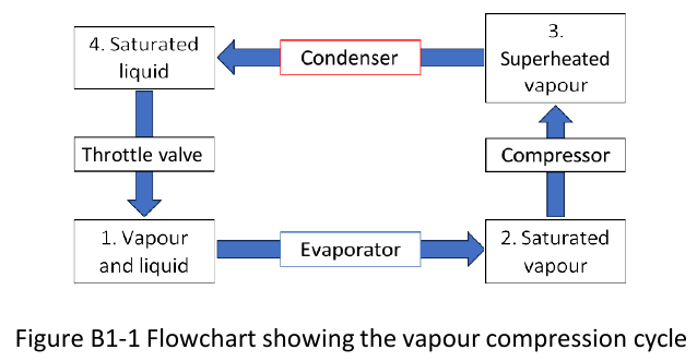
The flow diagram below (Figure B1-1) outlines the vapour compression refrigeration cycle.
Formulas you may need
- SFEE per unit mass for each component: ; throttle (on the formula sheet)
- Vapour-compression COP (flowchart numbering): (learn this)
- Isentropic compressor: (learn this)
- Residual volume: (on the formula sheet as )
- Molar from specific volume: (learn this)
- (a)[10]2:2Draw the vapour compression cycle on a Pressure-Volume diagram, making sure to indicate the locations of the numbered states in the flowchart above. Indicate the direction of the cycle, where heat enters and leaves the system and where any work is done.
- (b)[7]2:2Assuming the refrigerator employs HFC-134a as its working fluid, calculate the Coefficient of Performance for a refrigerator with a target temperature of and the condenser operates at 750 kPa. You may assume that the compressor operates isentropically.
- (c)[8]For the same refrigerator, determine the temperature and the residual volume of HFC-134a in the superheated vapour phase in . The molecular mass of HFC-134a is .