ENGR273 Summer 2026 Q1[VALID] official answers
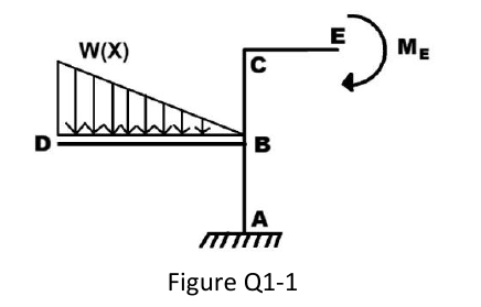
Figure Q1-1 shows a structure of negligible mass constrained by a fixed support at A, loaded by a distributed triangular normal load along beam DB and subjected to a concentrated moment at the end E of beam CE. Beam DB has length , and parts AB, BC and CE have each length . The expression of the distributed load is:
where is the horizontal coordinate along beam DB with origin at D, and is the value of the distributed load at end D.
Formulas you may need
- Resultant of a distributed load and its position (on the formula sheet)
- Positive shear and positive bending sign convention (pictures) (on the formula sheet)
- , , , (on the formula sheet)
- Maximum bending stress (on the formula sheet)
- Solid circle (on the formula sheet)
- Static equilibrium , , ; a fixed support gives two forces and a couple (learn this)
- (a)[6]2:2Draw the free-body-diagram of the entire structure, indicating ONLY the nonzero reactions and applied loads.
- (b)[6]2:2Calculate the reactions acting on the structure in figure Q1-1.
- (c)[8]Calculate and draw as accurately as possible the shearing load diagram along beam DB, and the bending moment diagram along column ABC.
- (d)[5]2:2Calculate the minimum diameter of the circular cross section of beam DB required for the maximum normal stress in any of the beam's cross sections not to exceed 150 MPa. Use kN/m and m.