ENGR5001 Lecture 2 worked example 2, LC circuit (slides 9-14)
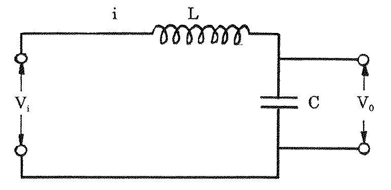
For the LC circuit in the figure (an inductor in series with a capacitor , input voltage applied across the pair, output voltage taken across the capacitor, loop current ):
Formulas you may need
- Inductor ; capacitor ; Kirchhoff's voltage law (learn this)
- Generalised second order form (learn this)
- (a)State the assumptions.
- (b)Develop the linear model relating to .
- (c)Convert the model into the generalised form and identify the input, output, , natural frequency, damping ratio and steady state gain. Which mechanical model has the same form?