Old spec 1.2 example, two tank hydraulic systemTutorialOld spec ENGR2022:115 min

ENGR202 (old spec) Control 1.2 Mechanistic Models, two tank hydraulic system (slides 14-17; generalised form in 1.3 slides 24-25)

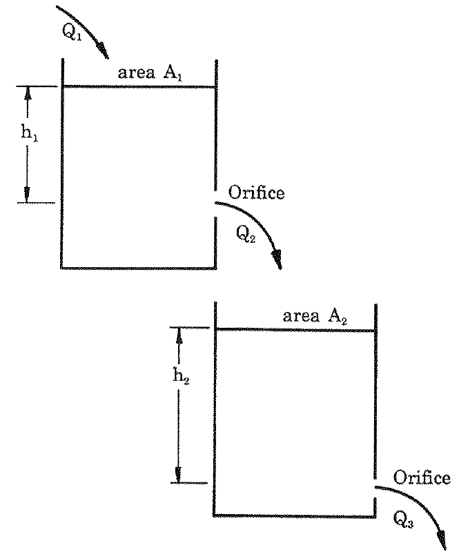
Two tanks are connected in cascade (see figure). Tank 1 (area A1A_1, head h1h_1) is filled at flow rate Q1Q_1 and drains through an orifice at flow rate Q2Q_2 into tank 2 (area A2A_2, head h2h_2), which drains through its own orifice at flow rate Q3Q_3. Assume, in addition to the single tank assumptions, that each outflow is proportional to its own head: Q2=K1h1Q_2 = K_1h_1 and Q3=K2h2Q_3 = K_2h_2.

Two tanks in cascade: Q_1 into tank 1 (area A_1, head h_1), Q_2 from tank 1 into tank 2 (area A_2, head h_2), Q_3 out of tank 2.
Formulas you may need
  • Volume balance Adhdt=Qin−QoutA\dfrac{dh}{dt} = Q_{in} - Q_{out}; linear orifice Q=KhQ = Kh (learn this)
  • Generalised second order form d2xdt2+2ζωndxdt+ωn2x=Ku(t)\dfrac{d^2x}{dt^2} + 2\zeta\omega_n\dfrac{dx}{dt} + \omega_n^2 x = Ku(t) (learn this)
  1. (a)
    Derive a first order model for each tank.
  2. (b)
    Eliminate Q2Q_2 to obtain a single model relating Q3Q_3 to Q1Q_1.
  3. (c)
    Put the model into generalised second order form, giving ωn\omega_n, ζ\zeta and the steady state gain. Show that the system can never oscillate.