ENGR202 (old spec) Control 2.4 Time Response, axial fan worked example (slides 18-20)
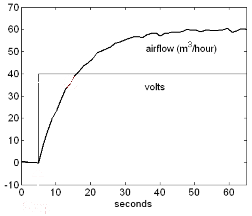
The figure shows a laboratory step test on an axial fan. The input voltage is stepped from 0 to 40 V at about s, and the airflow (m/hour) rises from 0 towards a steady value. The fan is to be modelled by the first order system , with the airflow and the input voltage.
Formulas you may need
- (for a step from zero) (learn this)
- At after the step: (learn this)
- (a)Estimate the steady state gain .
- (b)Estimate the time constant , and write down the model.
- (c)Using the model, what airflow is expected at steady state for a constant input of 20 V? Sketch the response to a step from 0 to 20 V.