ENGR202 Summer 2025 Q2[VALID]
This question concerns the heating system in a human occupied office building. The relationship between the indoor temperature and the applied voltage to a heater is approximated by Equation (2-1):
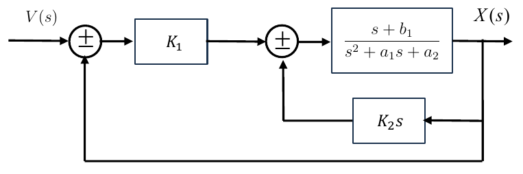
Figure Q2 shows a control system with two negative feedback loops.
Formulas you may need
- Steady state gain (set ) (learn this)
- Poles: roots of the denominator; zeros: roots of the numerator; stable if all poles have negative real parts (learn this)
- : , (learn this)
- Negative feedback rule ; series rule (learn this)
- (a(i))[6]The following questions are about the model given by Equation (2-1). Equation (2-1) was obtained by considering heat transfer and energy balance equations (details not important). Use this example to briefly explain the difference between data-based and mechanistic models. Suggest potential limitations of Equation (2-1), for example in its ability to represent real world temperature data and/or if it is subsequently used to design a control system.
- (a(ii))[6]State an algebraic equation for determining the steady state gain of Equation (2-1). Use your answer to determine the steady state indoor temperature for V, assuming initial conditions , , and coefficients , and .
- (a(iii))[6]Again with , and , what are the pole(s) and zero(s) of Equation (2-1). Plot and label the pole(s) on the complex -plane. State the stability condition, explaining the reason for your answer.
- (a(iv))[6]Still using , and , determine the natural frequency and damping ratio of the model given by Equation (2-1). Comment on what the damping ratio tells us about the dynamics of this model.
- (b(i))[4]The following questions are about the control system shown in Figure Q2. What is usually called and what does it represent? Briefly suggest how it might be chosen for the temperature control application.
- (b(ii))[9]Develop the closed-loop Transfer Function for Figure Q2 and hence show that the closed-loop characteristic equation is as follows: In addition, calculate the steady state gain of the closed-loop Transfer Function and comment on your answer.
- (b(iii))[6]Suggest and briefly describe two methods for designing the above controller, i.e., methods to determine suitable values of and in Figure Q2.
- (b(iv))[7]Figure Q2 represents an initial attempt at designing a controller for this problem. A more experienced control engineer states that Figure Q2 should be revised to include a more suitable control algorithm. Speculate on the reasons for their statement and suggest a more appropriate algorithm. Hints: your answer might refer to the model dynamics from part (a); the closed loop Transfer Function from part (b); and practical aspects of the temperature control application.