ENGR273 Summer 2026 Q3[VALID] official answers
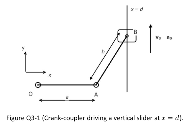
The planar mechanism in Figure Q3-1 comprises a crank OA (uniform slender rod of length , mass ) pinned at O, and a coupler AB (uniform slender rod of length , mass ) pinned at A and at the slider point B. Point B is a frictionless slider of mass constrained to move along the vertical guide at . At the instant shown, OA is horizontal along , so . The slider is at with . The slider velocity and acceleration are known and upward:
Neglect gravity and all frictions of the whole system. Positive angular sense is counterclockwise .
Formulas you may need
- Rotation about a fixed axis: , (learn this)
- Relative velocity (learn this)
- Relative acceleration (learn this)
- Equations of motion , (or about a fixed pin) (learn this)
- Slender rod , about an end (learn this)
- (a)[8]2:2Draw the free-body diagrams and kinetic diagrams for OA, AB, and the slider at B. Clearly state your axes and indicate all unknown reactions at pins/guide.
- (b)[8]2:2Determine the instantaneous angular velocities and , expressed in terms of , , , and .
- (c)[9]Determine the instantaneous angular accelerations and , expressed in terms of , , , , and .