Tutorial 3 Problem 1Exercise sheetCurrent spec2:220 min

ENGR5004 Statics Tutorial Sheet 3, Problem 1 official answers

Part (a) refers to the state of plane stress sketched in fig. 1-a; parts (b) to (e) refer to the state of plane stress sketched in fig. 1-b.
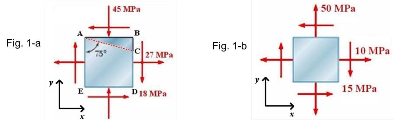
Fig. 1-a: square element ABDE with 27 MPa tension on the vertical faces, 45 MPa compression on the horizontal faces and 18 MPa shear (downward on the right face); oblique face AC from corner A, at 75 degrees to side AE. Fig. 1-b: element with 10 MPa tension on the vertical faces, 50 MPa tension on the horizontal faces and 15 MPa shear (downward on the right face).
Formulas you may need
  • Stress transformation: σx′=σx+σy2+σx−σy2cos⁡2θ+τxysin⁡2θ\sigma_{x'} = \dfrac{\sigma_x+\sigma_y}{2} + \dfrac{\sigma_x-\sigma_y}{2}\cos2\theta + \tau_{xy}\sin2\theta, τx′y′=−σx−σy2sin⁡2θ+τxycos⁡2θ\tau_{x'y'} = -\dfrac{\sigma_x-\sigma_y}{2}\sin2\theta + \tau_{xy}\cos2\theta (learn this)
  • Principal directions: tan⁡2θp=2τxyσx−σy\tan2\theta_p = \dfrac{2\tau_{xy}}{\sigma_x-\sigma_y}; principal stresses σmax,min=σx+σy2±(σx−σy2)2+τxy2\sigma_{max,min} = \dfrac{\sigma_x+\sigma_y}{2} \pm \sqrt{\left(\dfrac{\sigma_x-\sigma_y}{2}\right)^2 + \tau_{xy}^2} (learn this)
  • Maximum shear: tan⁡2θs=−σx−σy2τxy\tan2\theta_s = -\dfrac{\sigma_x-\sigma_y}{2\tau_{xy}}, τmax=(σx−σy2)2+τxy2\tau_{max} = \sqrt{\left(\dfrac{\sigma_x-\sigma_y}{2}\right)^2 + \tau_{xy}^2}, normal stress σ′=σx+σy2\sigma' = \dfrac{\sigma_x+\sigma_y}{2} (learn this)
  1. (a)
    determine normal and shear stresses acting on oblique face AC of shaded triangular element shown.
  2. (b)
    determine orientation of principal axes and sketch them in xyxy Cartesian system indicated in figure,
  3. (c)
    determine principal stresses and shear stress on principal planes,
  4. (d)
    determine orientation of maximum shear stress axes (i.e. axes orthogonal to planes of maximum shear stress),
  5. (e)
    determine maximum shear stress and corresponding normal stress