ENGR216 Summer 2018 Q A2[VALID] official answers
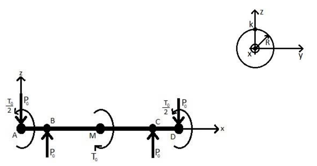
Consider the free-body-diagram of the axle AD depicted in the left plot of Figure A2, with dimensions and . The axle cross section, depicted in the right plot of Figure A2, has radius . The axle is subject to an engine torque applied at M, two resistive torques applied at A and D, two vertical loads applied at A and D, and two vertical reactions applied at B and C.
Formulas you may need
- Sign convention for positive shear and bending, , (on the formula sheet)
- Bending stress ( measured from the neutral axis; here the vertical coordinate is ), (on the formula sheet; also printed in this paper's appendix)
- Torsion , (learn this; printed in this paper's appendix but not on the 2026 sheet)
- Principal stresses , (learn this; printed in this paper's appendix but not on the 2026 sheet)
- Maximum in-plane shear ; Mohr's circle centre and radius (learn this)
- (a)[4]2:2Determine the expression of the bending moment , shear load and torsional load along the entire axle.
- (b)[3]2:2Sketch , and along the entire axle.
- (c)[4]State in which portion ( interval) of the axle one has a plane stress state on the axle surface and explain why.
- (d)[7]Determine the magnitude of the maximum normal stress at the point K indicated in the right plot of Figure A2 acting on the axle surface at any axial position between B and M, and state if this stress is tensile or compressive.
- (e)[3]2:2Determine the magnitude of the maximum shear stress at the point K indicated in the right plot of Figure A2 acting on the axle surface at any axial position between B and M.
- (f)[4]2:2Calculate the centre coordinates and the radius of Mohr's circle referring to the axle surface point K at any position between B and M, and draw as accurately as possible Mohr's circle in the - plane, indicating in such plane the points corresponding to principal stresses and maximum shear stress.