ENGR5004 Statics Tutorial Sheet 4, Problem 2 official answers
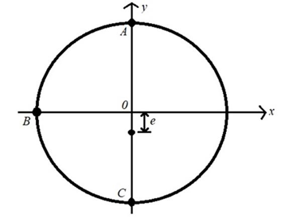
A cantilevered metal beam has length m, circular cross section of radius , and is subject to a compressive axial load kN applied at distance from the section centre, as indicated in the figure below. The material of the beam has Young's modulus GPa and allowable normal stress of 150 MPa.
Parts (b) to (e): assuming and using the value of obtained at (a).
Formulas you may need
- Euler critical load ; fixed-free (on the formula sheet)
- Solid circle , (on the formula sheet)
- Eccentric axial loading: , , (on the formula sheet)
- Maximum in-plane shear for a uniaxial surface element: ; principal axes along the stress directions, maximum-shear axes at (learn this)
- (a)Assuming , and a buckling safety factor of 2.0, determine the minimum radius of the cross section required for yield- and buckling-free operation.
- (b)determine distance (with sign) of the neutral axis from the -axis. Briefly comment on this result with regard to the sign of the normal stress in the section, and sketch the diagram of the resulting normal stress along the axis of the section clearly indicating the neutral axis;
- (c)at positions A, B and C determine the normal stress acting on the beam cross section, and the maximum shear stress on beam surface.
- (d)Briefly comment on results of (c) with regard to capability of the designed beam to withstand the considered eccentric axial load.
- (e)At points A, B and C determine the orientation of the principal axes and the maximum shear axes with respect to the axis coinciding with the axis of the beam.