ENGR273 Summer 2026 Q2[VALID] official answers
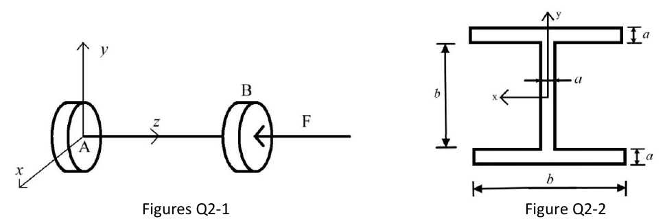
Figure Q2-1 shows a rod of negligible mass of length subjected to a compressive axial load . The rod is constrained by a fixed support at both end A and end B. The rod's cross section is depicted in Figure Q2-2, in which .
Formulas you may need
- Euler critical load , , (on the formula sheet)
- Effective lengths: fixed-free , pinned-pinned , fixed-pinned , fixed-fixed (on the formula sheet)
- Rectangle , , (on the formula sheet)
- Parallel-axis theorem (or build the I-section by subtracting rectangles) (learn this)
- Axial stress ; buckling safety factor (learn this)
- (a)[6]Assuming that the compressive load exceeds by a small amount Euler's critical load, determine and clearly state if the rod will buckle in the or plane.
- (b)[6]Draw as accurately as possible the shape of the buckled rod, labelling the two Cartesian axes defining the plane in which the rod buckled, and fulfilling the applied constraints in the drawn schematic.
- (c)[7]Using kN, allowable normal stress of 100 MPa, Young's modulus of 200 GPa, m and a safety factor of 2 for the buckling critical load, calculate the minimum value of required for the rod not to buckle and not to yield.
- (d)[6]Assuming that the rod designed in part (c) is used with the fixed support at A but no constraint at B, and using a safety factor of 2 in the buckling analysis, determine and state if the rod will buckle or yield under the new constraint set-up.