ENGR216 Summer 2024 Statics Q A1[VALID]
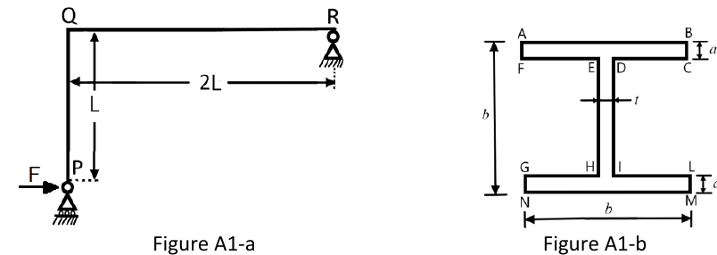
Figure A1 shows a constrained structure of negligible mass constrained by a roller at end P and a pin at end R. End P is loaded by a horizontal concentrated load , as indicated in Figure A1.
Formulas you may need
- Equilibrium of a rigid body in the plane: , , (learn this)
- Internal forces by the method of sections; sign convention for positive shear and positive bending as pictured, (on the formula sheet)
- Pure bending , (on the formula sheet)
- Combined axial force and bending (eccentric loading form) (on the formula sheet)
- Rectangle (on the formula sheet); I-section by subtraction or by three rectangles with the parallel-axis theorem (learn this)
- Elastic curve for the curvature argument in (d) (learn this; on the 2025 sheet but not the 2026 one)
- (a)[4]ThirdDraw the free-body-diagram of the entire structure, indicating only nonzero reactions and applied loads.
- (b)[4]2:2Calculate the reactions acting on the considered structure.
- (c)[6]2:2Calculate the axial load distribution , the sharing load distribution and the bending moment distribution along members PQ and QR.
- (d)[6]Draw as accurately as possible the bending moment diagram along PQ and QR and the elastic curve of the whole structure, explaining why the curvature of the elastic curve is consistent with the diagram of in both PQ and QR.
- (e)[5]Calculate the minimum length required for the magnitude of the maximum normal stress in the cross section of PQ at distance from P not to exceed 120 MPa. The beam cross section is reported in Figure A1-b. Use mm, mm and kN. The section is positioned so that the neutral axis of the bending moment alone is parallel to side AB.