ENGR216 Summer 2023 Statics Q A2[VALID]
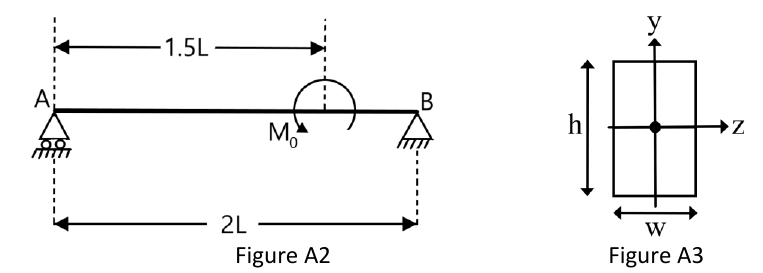
Figure A2 shows a beam of negligible mass with flexural rigidity and length . The beam is subjected to a pointwise moment at point P at a distance of from the left end A.
Formulas you may need
- Equilibrium of a rigid body: , ; a couple has the same moment about every point (learn this)
- Positive shear and bending sign convention pictures; , (on the formula sheet)
- Elastic curve: , two constants per segment, boundary and continuity conditions (learn this; on the 2025 sheet but not the 2026 one)
- Rectangle: about the horizontal centroidal axis (on the formula sheet)
- (a)[5]2:2Draw the free body diagram of the loaded beam, indicating only nonzero reactions and applied loads (3 marks). Explain if and why the reactions would change if the moment was applied at the midpoint of the beam (2 marks).
- (b)[4]Draw the elastic curve of the beam as accurately as possible, accounting for the suppressed degrees of freedom.
- (c)[5]2:2Determine the equation of the bending moment along the entire beam as a function of and .
- (d)[6]Knowing that the vertical displacement along the beam axis is: state what are the four conditions to determine the constants , , , and (3 marks), and calculate them (3 marks).
- (e)[5]2:2As shown in Figure 3, the beam has a rectangular cross section of width and height . Determine the minimum value of such that the magnitude of the vertical displacement of the beam at does not exceed 1 mm. Use kNm, mm, m and GPa.