ENGR216 Summer 2025 Q A2[VALID] official answers
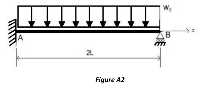
Figure A2 shows a beam of negligible mass with flexural rigidity and length . The beam is constrained by a fixed support at end A and a roller at end B, and is subjected to a uniform distributed load .
Formulas you may need
- Equilibrium , , ; a fixed support gives two forces and a couple, a roller one force; degree of indeterminacy = unknown reactions minus independent equilibrium equations (learn this)
- Elastic curve , slope (learn this; on the 2025 sheet but not the 2026 one)
- Load, shear and moment: , , with the positive shear and positive bending pictures (on the formula sheet)
- Slope is extreme where ; deflection is extreme where (learn this)
- Pure bending (on the formula sheet)
- Rectangle , so a square of side has , (on the formula sheet)
- (a)[4]2:2Draw the free-body-diagram of the entire structure, indicating ONLY the nonzero reactions and applied loads, and state if the structure is statically determinate or indeterminate, justifying your answer.
- (b)[6]Determine all nonzero reactions acting on the beam as functions of and , knowing that the vertical displacement of its cross sections is: where denotes the position along the axis of the beam.
- (c)[4]2:2Draw as accurately as possible the bending moment diagram of the beam and the deformed shape of its mean line (elastic curve).
- (d)[4]Calculate the positions along the beam at which the elastic curve has maximum slope as functions of .
- (e)[7]2:2Knowing that the beam has square cross-section, determine the minimum side length of the cross-section such that the maximum normal stress in the cross-section at end A does not exceed the material's allowable normal stress of 200 MPa. Use kN/m and m.